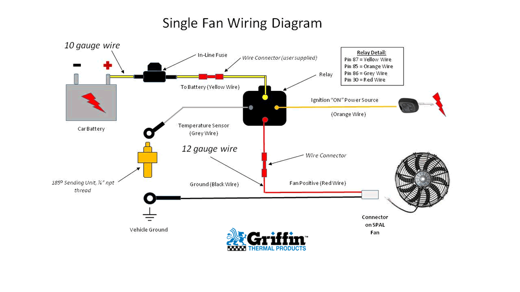
Single Fan Wiring Diagram

Single Electric Fan Wiring Diagram This wiring diagram illustrates the connections for a ceiling fan and light with two switches, a speed controller for the fan and a dimmer for the lights. use this arrangement when the source is at the switches. here the input of each controller is spliced to the black source wire with a wire nut. from there, 3 wire cable runs to the ceiling. As expected, the neutral and grounds are simply tied together and all is well. 4. switching the light and fan from separate switches (two switches) this is the most versatile way to electrically wire a ceiling fan with a light kit. it allows for separate control over both the fan and the light in the room.

Single Fan Wiring Diagram Ceiling fan diagrams fan wiring diagram with power entering the switch box and the load wire connected to the blue wire for the light and the black wire for the fan motor. the above ceiling fan wiring diagram depicts the power going into the switches’ electrical box first. then a switched hot and a neutral go up to the ceiling mounted. Follow these steps if wiring with two switches for separate control of the fan and light: bring the power supply cable and the cable from the fan to the switches. connect the power cable’s hot wire and one of the fan’s hot wires to one of the switches. connect the power cable’s hot wire and the fan’s other hot wire to the second switch. Connect the green wire to your household ground wire (copper bare wire). connect the black wires together. connect the blue wires together or the blue wire to the black wire for lights. follow the same step for ceiling fans without lights. this will allow you to add a light kit later on without having to rewire the fan. To do this, follow the instructions below: first of all, connect the green yellow as a ground wire to the incoming ground earth wire. now, connect the blue wire as neutral to the incoming neutral from the main db. connect the incoming brown as live wire to the single way switch.

Single Electric Fan Wiring Diagram Connect the green wire to your household ground wire (copper bare wire). connect the black wires together. connect the blue wires together or the blue wire to the black wire for lights. follow the same step for ceiling fans without lights. this will allow you to add a light kit later on without having to rewire the fan. To do this, follow the instructions below: first of all, connect the green yellow as a ground wire to the incoming ground earth wire. now, connect the blue wire as neutral to the incoming neutral from the main db. connect the incoming brown as live wire to the single way switch. The fan control switch usually connects to the black wire and the light kit switch to the red wire of a 3 way cable. in this diagram, the black wire of the ceiling fan is for the fan, and the blue wire is for the light kit. ground connection diagram is shown separately. ceiling fan switch wiring diagram using two 2 wire nm’s. The black wire, or the hot wire, is the backbone of the ceiling fan circuit that connects the fan with the switch outlet. the neutral white wires direct the additional electricity to the breaker box and maintain a closed electrical path. green wires are insulated cables that keep the fan from the consequences of overvoltage.

Single Electric Fan Relay Wiring Diagram The fan control switch usually connects to the black wire and the light kit switch to the red wire of a 3 way cable. in this diagram, the black wire of the ceiling fan is for the fan, and the blue wire is for the light kit. ground connection diagram is shown separately. ceiling fan switch wiring diagram using two 2 wire nm’s. The black wire, or the hot wire, is the backbone of the ceiling fan circuit that connects the fan with the switch outlet. the neutral white wires direct the additional electricity to the breaker box and maintain a closed electrical path. green wires are insulated cables that keep the fan from the consequences of overvoltage.

Comments are closed.