What Are Lines Types Of Lines In Engineering Drawing

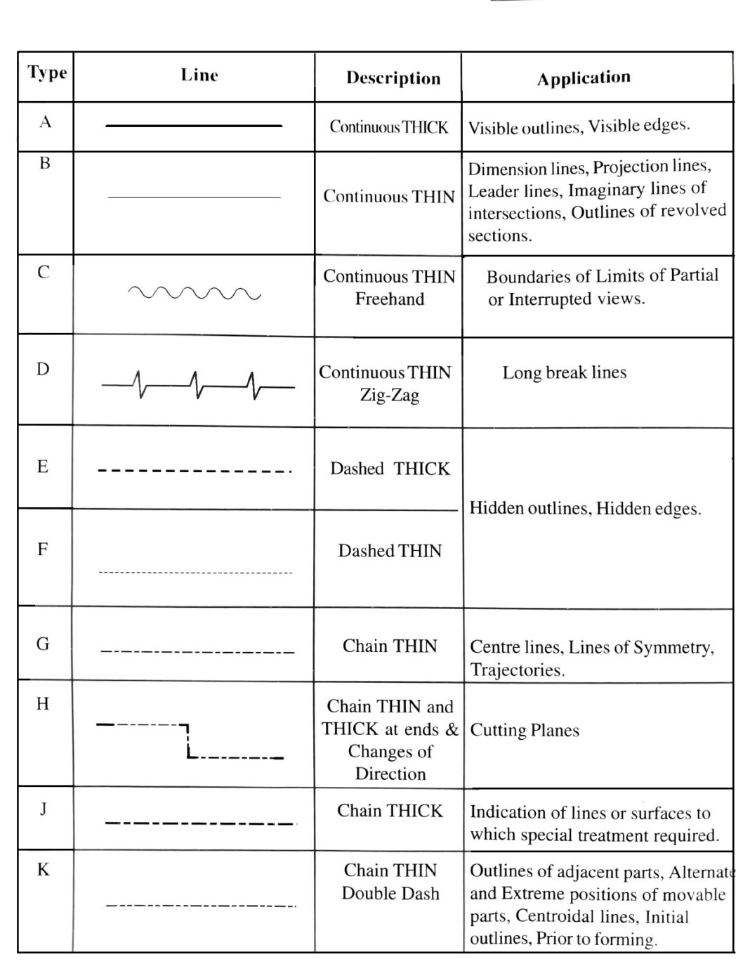
Engineering Drawing 8 Tips To Improve Engineering Drawing Skills Straight and curved lines are parallel when the shortest distance between them remains constant. again, lines are differentiated as thick lines (0.6 mm thickness), thin lines (0.3 mm thick), continuous lines, dashed lines, freehand lines, zigzag lines, chain lines, etc. in this article, we will learn the various types of lines that are widely. Following are the different types of lines used in engineering drawing: a type – continuos thick. b type – continuous thin. c type – continuous thin freehand. d type – continuous thin zig zag. e type – dashes thick. f type – dashes thin. g type – chain thin. h type – chain thin and thick.

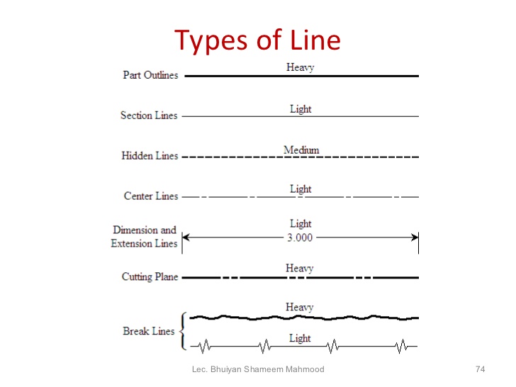
Different Types Of Lines In Engineering Drawing Classification Of Linesођ Continuous thin line. the continuous thin line is the most frequently used line type on engineering drawings. these lines are solid and has no break in them. here is the list of cases where the continuous thin line will be used: imaginary lines of intersection. dimension line. projection lines. The thickness relates to the importance of the line on a drawing. the typical leads used are h, 2h, 4h (2 mm), and or 0.03 mm, 0.05 mm, 0.07 mm, and 0.09 mm. line weight on a drawing varies from a thin line to a thicker line. the line types typically used on nkba drawings are illustrated in figure 1. figure 1 line types used on floor plan. Leader lines. orthographic projection lines. section lines. visible lines. these are various types of lines commonly used in technical drawings, engineering, and architectural drafting: break lines: break lines are used to represent a long object or feature that is too large to be shown in its entirety on a drawing. Technical drawings convey objective facts, and those facts are represented by the lines and text on the drawing. different styles and thicknesses of lines are used to convey different aspects of the object being drawn. text must be printed and legible. dimensions must be clearly located with extension lines and arrows.

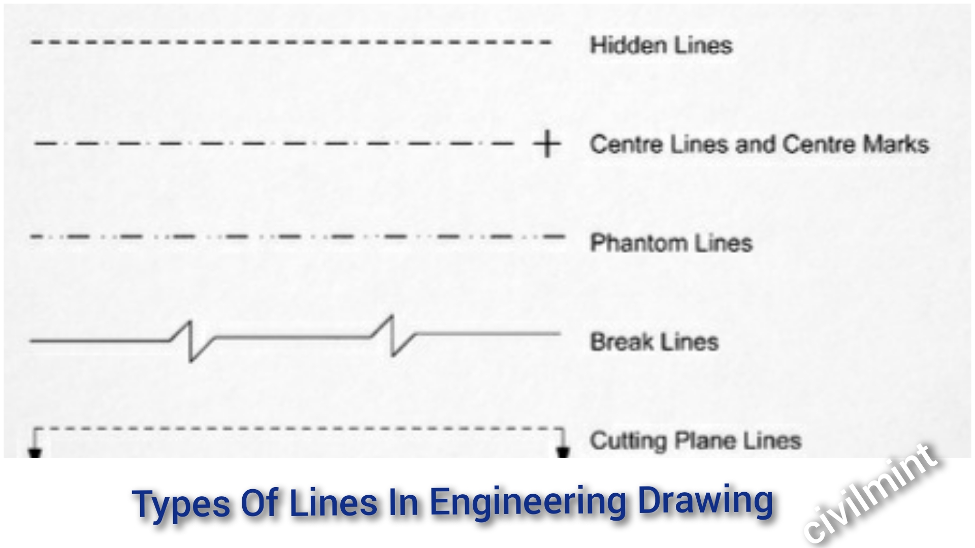
Types Of Lines In Engineering Drawing Civilmint Com Leader lines. orthographic projection lines. section lines. visible lines. these are various types of lines commonly used in technical drawings, engineering, and architectural drafting: break lines: break lines are used to represent a long object or feature that is too large to be shown in its entirety on a drawing. Technical drawings convey objective facts, and those facts are represented by the lines and text on the drawing. different styles and thicknesses of lines are used to convey different aspects of the object being drawn. text must be printed and legible. dimensions must be clearly located with extension lines and arrows. The width of the line should be chosen from one of the following. 0.13 mm, 0.18mm, 0.25 mm, 0.35 mm, 0.50mm, 0.70mm, 1.0mm, 1.4 mm, and 2.0 mm. the series is based on the common ratio of 1:√2 or 1:1.4. generally, lines of three different widths specified as extra wide, wide, and narrow lines are used in engineering drawing works. Center lines. center lines (figure \(\pageindex{5}\)) are used in drawings for several different applications. the meaning of a center line is normally determined by how it is used. center lines are thin, alternating long and short dashes that are generally used to show hole centers and center positions of rounded features, such as arcs and radii.

10 Different Types Of Lines Used In Engineering Drawing The width of the line should be chosen from one of the following. 0.13 mm, 0.18mm, 0.25 mm, 0.35 mm, 0.50mm, 0.70mm, 1.0mm, 1.4 mm, and 2.0 mm. the series is based on the common ratio of 1:√2 or 1:1.4. generally, lines of three different widths specified as extra wide, wide, and narrow lines are used in engineering drawing works. Center lines. center lines (figure \(\pageindex{5}\)) are used in drawings for several different applications. the meaning of a center line is normally determined by how it is used. center lines are thin, alternating long and short dashes that are generally used to show hole centers and center positions of rounded features, such as arcs and radii.

Types Of Lines Engineering Drawing Mechgate Youtube

Comments are closed.