Power Dissipation In Cmos Circuits Back To Basics

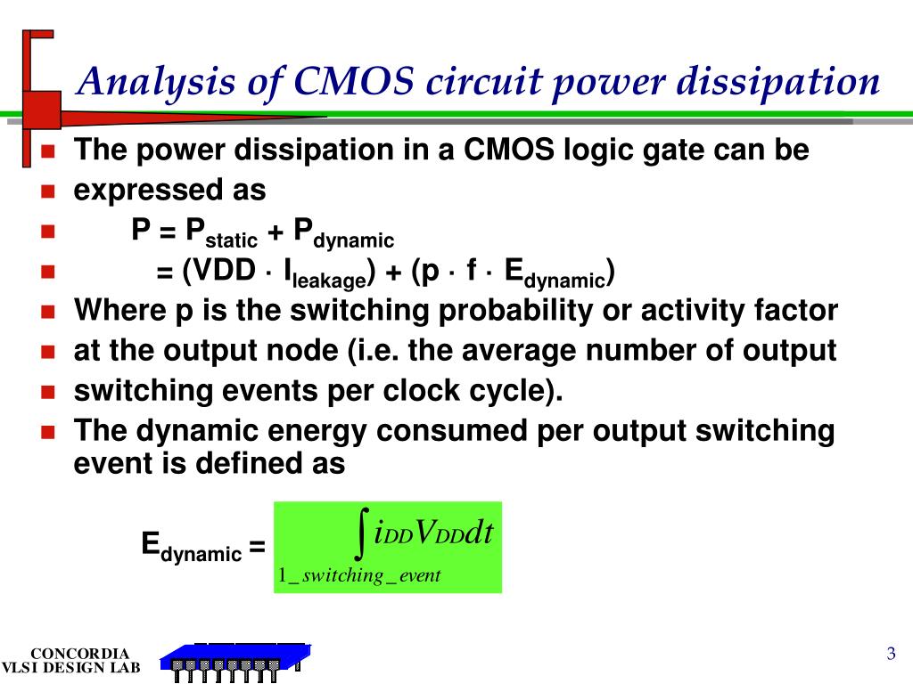
Power Dissipation In Cmos Circuits Back To Basics Youtube Hello everyone,this video explains different types of power dissipation in cmos circuits.check it out to gain an insight on the following topics:a) static po. Review: dynamic power. each charge discharge cycle dissipates total energy e = c v 2 vdd l dd. to compute power, account for switching the circuit at frequency f. typically, output does not switch every cycle, so we scale the power by the probability of a transition α.

Ppt Revisit Cmos Power Dissipation Powerpoint Presentation Free Download Id Electricity cost cand easily be 40% of total cost. current trends indicate a further increase in this percentage. power delivery. itanium consumes 130w at 1.3v. ir and ldi dt drops reduce supply at devices. battery life. low energy extremely critical for mobile hand held applications. li ion batteries: 100 150whr kg. Figure 7.1.1 7.1. 1: a cmos inverter consists of two complementary mosfets in series. for constant voltage input, the circuit has two stable states, as shown in figure 7.2.2. because one of the transistors is always off in steady state, the circuit ideally has no static power dissipation. figure 7.1.2 7.1. 2: the two steady state configurations. We see this relationship in the basic formula for electric power: p = i × v p = i × v. equation 1. though a cmos inverter doesn’t require current flow in its steady state, power is consumed during its logic transitions. this dynamic power loss comes in two types: switching power dissipation. Power dissipation reduction is another essential goal in the designs. in a cmos circuit, overall power dissipation may be stated as the sum of three major elements: static power dissipation (due to leakage current when the circuit is idle) dynamic power dissipation. 2.1 switching power dissipation.

Ppt Power Dissipation In Cmos Powerpoint Presentation Free Download Id 54095 We see this relationship in the basic formula for electric power: p = i × v p = i × v. equation 1. though a cmos inverter doesn’t require current flow in its steady state, power is consumed during its logic transitions. this dynamic power loss comes in two types: switching power dissipation. Power dissipation reduction is another essential goal in the designs. in a cmos circuit, overall power dissipation may be stated as the sum of three major elements: static power dissipation (due to leakage current when the circuit is idle) dynamic power dissipation. 2.1 switching power dissipation. Cmos power dissipation refers to the amount of power dissipated by complementary metal oxide semiconductor (cmos) integrated circuits (ics) during operation. cmos is widely used in modern electronic devices, such as microprocessors, memory chips, and other digital logic circuits, due to its low power consumption, high noise immunity, and. Maximum allowable power dissipation, p d, describes the mosfet maximum dissipation for the maximum allowable junction temperature, t j(max). typically, this rating specifies the case temperature.

Comments are closed.