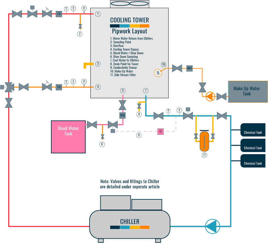
Piping And Instrumentation Diagram Cooling Tower

Cooling Tower Piping Layout And Diagrams Constructandcommission Cooling tower | piping layout and diagrams. to allow the cooling towers to operate correctly, in line with the design and efficiently, various systems will need to be connected to allow them to work. depending upon how the towers are installed will mean different configurations would be required. the pipework that is commonly connected to the. Troubles do occur occasionally, however, and these troubles can be classified as caused by: 1. incorrect pump head estimation. 2. pump cavitation and loss of pumping ability, as caused by inadequate pump suction pressure. 3. air in pump suction; as caused by tower pan vortex, pan drain down or faulty bypass. 4.

Open Circuit Cooling Tower P Id Cooling Tower Piping And Instrument A piping & instrumentation diagram (p&id) is a schematic layout of a plant that displays the units to be used, the pipes connecting these units, and the sensors and control valves. standard structures located on a p&id include storage tanks, surge tanks, pumps, heat exchangers, reactors, and distillation columns. The cooling tower p&id symbol is used in a piping and instrumentation diagram to visually represent the equipment connected to the process pipeline. initially, seeing the symbol may be hard to read, but once you go through the legend sheet of the p&id diagram, you will get to know the meaning of the symbol. for example, a solenoid valve is. Cooling tower piping: when designing a cooling tower system for free cooling applications, several piping details should be considered to ensure proper winter operation of the unit. a cooling tower bypass needs to be incorporated into the system design to allow water to “bypass” the tower’s water distribution system as a means of capacity. In the design and operation of cooling towers, a piping schematic plays a crucial role in ensuring the efficient and effective cooling of water. this schematic provides a detailed representation of the piping system within a cooling tower, including the flow paths, pipe sizes, valves, and other components. it serves as a roadmap for engineers.

Comments are closed.