Peltier Wiring Diagram Wiring Diagram Pictures

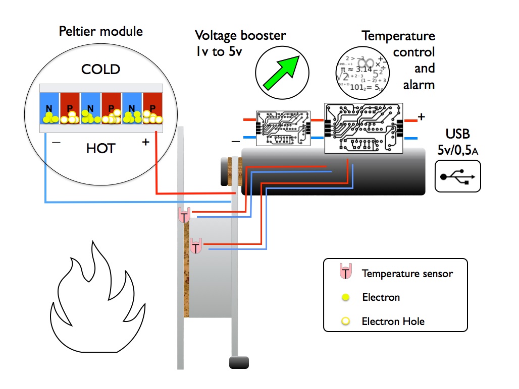
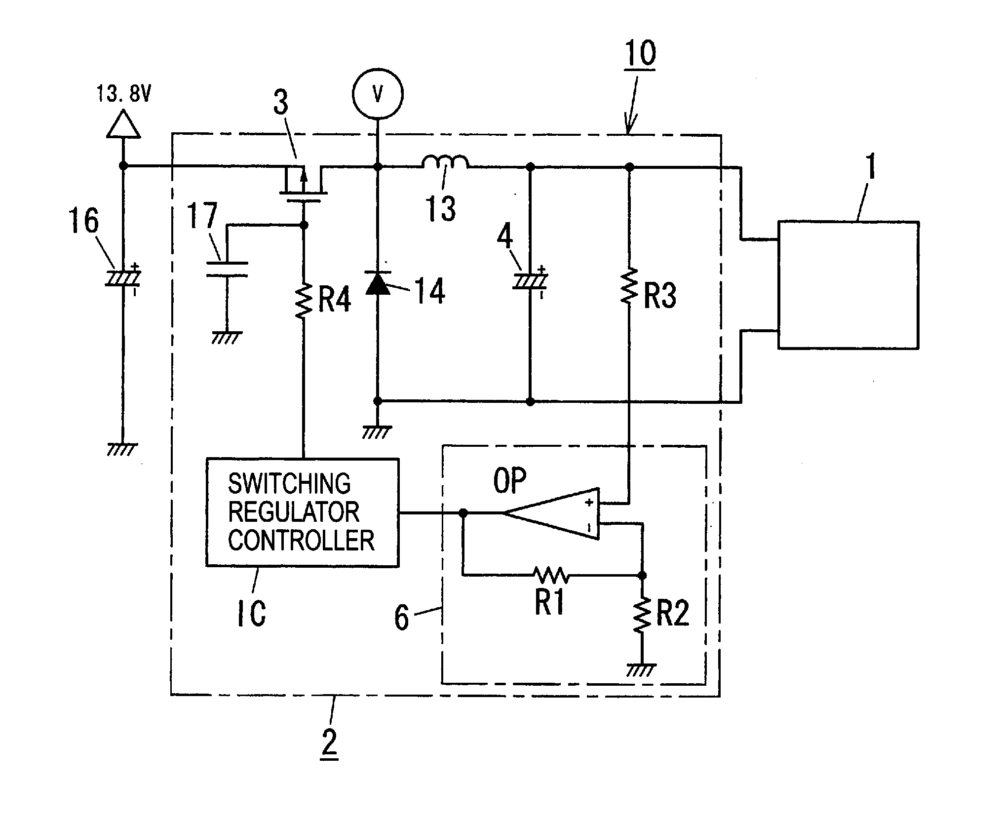
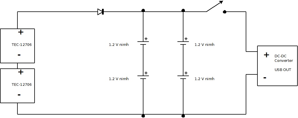
Peltier Wiring Diagram Wiring Diagram Pictures Peltier cooler wiring diagrams are essential for anyone looking to install or modify a peltier cooling device. these diagrams provide detailed instructions on how to wire the device to a power source, as well as providing other helpful information like terminal numbers, wire colors, and fuse ratings. knowing how to read and interpret peltier. In a nutshell, a peltier module circuit diagram is a visual guide showing how electrical current flows into and out of the peltier module. it provides an easy to follow reference for installing and connecting the module, as well as the proper voltage and resistance settings. the diagram also allows users to see the relationship between the.

Peltier Wiring Diagram Wiring Diagram Pictures Peltier elements should not be driven with alternating current as this will cause thermal stress, whitch is harmful to them. you should implement a galvanic isolation to protect yourself. so you will have to look for a psu that is rated for 4×12v×6a = 288 w at 48 v. cite. The core of any thermoelectric cooler wiring diagram is the power source, usually a dc power supply connected to the positive and negative terminals of the thermoelectric module. this is typically connected to the thermoelectric cooler's fan, along with the optional fan speed control. in addition, the thermoelectric module needs to be connected. The idea of the electrical or wiring diagram is to trace the flow of power and signals between the sources, control devices, and final loads. these will usually be drawn in a line format from left to right, but are not analogous to ladder diagrams. reading electrical diagrams is one of the most important skills for anyone in a troubleshooting. Wiring schematics symbols are a crucial tool for electrical engineers and technicians. these symbols represent various electrical components, such as resistors, capacitors, and switches, and help professionals create accurate and detailed wiring diagrams. by using standardized symbols, engineers can easily communicate and understand complex.

Peltier Wiring Diagram Wiring Diagram Pictures The idea of the electrical or wiring diagram is to trace the flow of power and signals between the sources, control devices, and final loads. these will usually be drawn in a line format from left to right, but are not analogous to ladder diagrams. reading electrical diagrams is one of the most important skills for anyone in a troubleshooting. Wiring schematics symbols are a crucial tool for electrical engineers and technicians. these symbols represent various electrical components, such as resistors, capacitors, and switches, and help professionals create accurate and detailed wiring diagrams. by using standardized symbols, engineers can easily communicate and understand complex. The most common resistor symbols include a zigzag line and a rectangle with a diagonal line. these symbols indicate the presence of resistance in a circuit, which limits the flow of electrical current. 5. lamp and light symbols. lamp and light symbols are used to represent lighting elements in wiring diagrams. Step 2: recognize major components. before you dive into the wires and connections, take a high level view of the major components included in the system. identify transformers, motors, solenoid valves, motor starters, lighting ballasts, microprocessors, switches, and other significant components by their symbols.

Comments are closed.