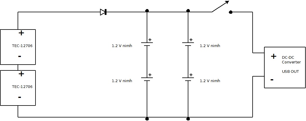
Peltier Wiring Diagram

Power Supply Peltier Wiring Diagram Electrical Engineering 42 Off Step 4: arduino setup: connecting the peltier unit. put the peltier module between two metal plates. the module should be placed in between the two plates to guide the heat away from the module. also, a bit of thermal paste should be used between the module and metal plates. In a nutshell, a peltier module circuit diagram is a visual guide showing how electrical current flows into and out of the peltier module. it provides an easy to follow reference for installing and connecting the module, as well as the proper voltage and resistance settings. the diagram also allows users to see the relationship between the.

Peltier Wiring Diagram Wiring Diagram Pictures I’m using a dupont cable (in fact 2 cables because it was a bit loose with a single one) to connect these ports together. you can now connect the peltier and computer fans to the k0 and gnd connector of the w1209 digital thermostat. check the wire diagram to make sure that you wired everything properly before turning on the mini fridge!. A sensor will control the alimentation by turning the peltier module on and off, depending on the settings. check the wire diagram at the end of this post to see how to connect everything to the peltier device and the power supply. the tec 12706 peltier module can in theory use up to 6 amps, so it needs a good power supply. Step 6: wiring the peltier module. wiring the peltier module is a crucial step in the construction of your peltier cpu cooler. this step involves connecting the peltier device to the power supply, ensuring proper electrical connections for optimal cooling performance. here’s a step by step guide on how to wire the peltier module: 1. A peltier device is a 2 wire semiconductor device having two surfaces that generate hot and cold temperatures across them in response to electricity supplied on its wire terminals. basically it works on the principle of thermo electric effect (opposite of seebeck effect) where a potential difference is used for making or producing hot and cold.

Peltier Wiring Diagram Wiring Diagram Pictures Step 6: wiring the peltier module. wiring the peltier module is a crucial step in the construction of your peltier cpu cooler. this step involves connecting the peltier device to the power supply, ensuring proper electrical connections for optimal cooling performance. here’s a step by step guide on how to wire the peltier module: 1. A peltier device is a 2 wire semiconductor device having two surfaces that generate hot and cold temperatures across them in response to electricity supplied on its wire terminals. basically it works on the principle of thermo electric effect (opposite of seebeck effect) where a potential difference is used for making or producing hot and cold. By popular request, here is a video showing you how to connect all those cables from your fans and peltiers to a power source such as a battery. A peltier circuit diagram is a visual representation of how this process works. at its most basic, a peltier circuit consists of two distinct layers. the first layer is composed of two materials with different electrical properties, such as copper and aluminum. these two materials are connected together in a circuit.

Comments are closed.