Pcb Layout Guidelines Can Bus Pcb Circuits

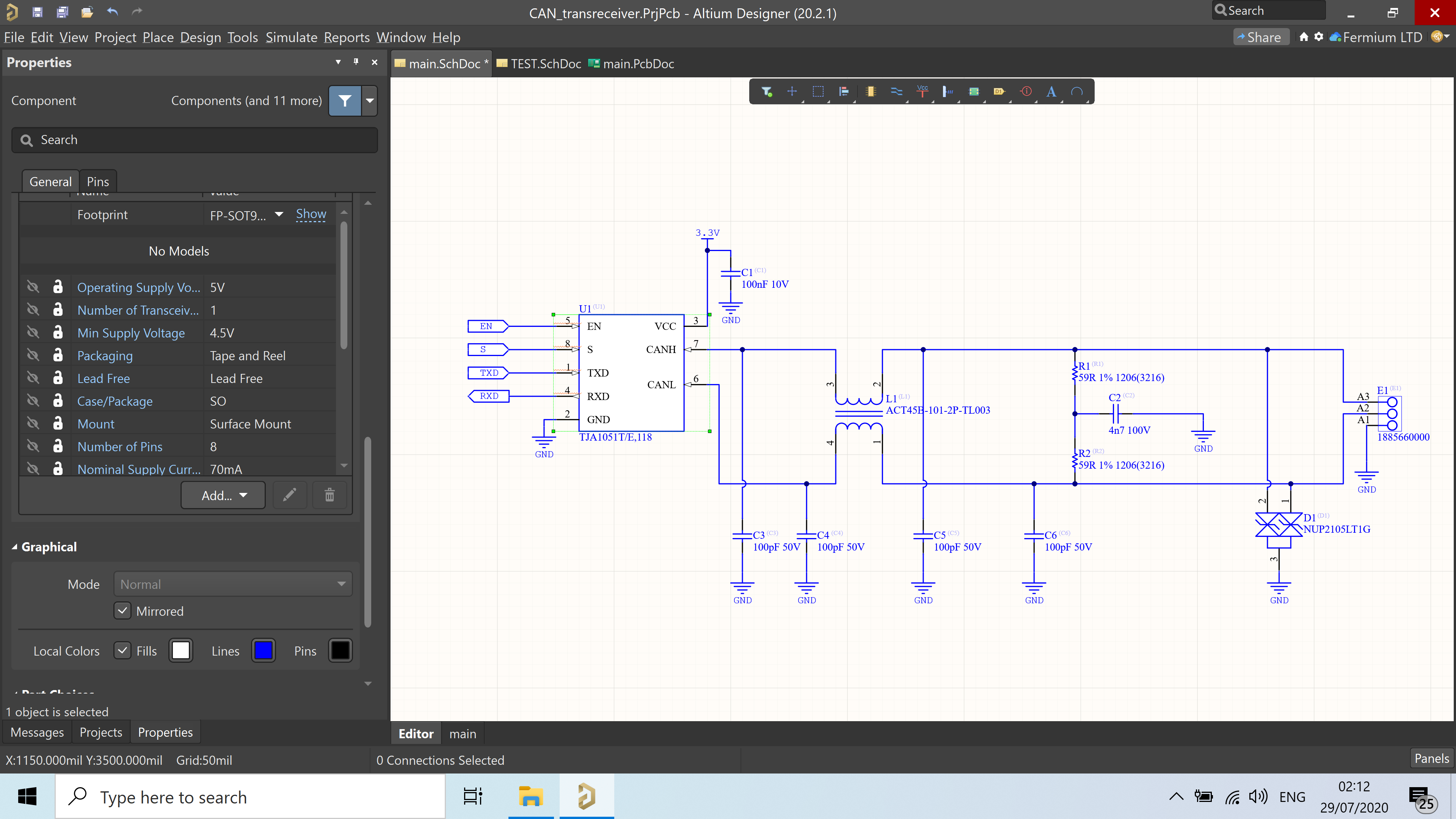
Designing Can Bus Circuitry Can Bus Pcb Layout Guidelines Designing can bus circuitry: can bus pcb layout guidelines. there are three main components in a can bus node: the can bus controller implements all the low level features of the network protocol, iso 11898–1, while the transceiver communicates with the physical layer. different transceivers are required for different physical layers, such as. The termination resistors are used to suppress electrical reflections on the bus. the termination resistor value is dependent on the number of nodes present in the network, and these values can be in the range of 100 to 130 Ω. typically, a nominal value of 120 Ω is placed between the can h and can l at both end points of the can network.

Designing Can Bus Circuitry Can Bus Pcb Layout Guidelines Remember to provide for 120ohm termination resistors (across the can bus lines) at the transmitting end and the last receiver on the bus. connector: should be fine as long as the contacts are clean. separate the can bus pins from other high speed pins with a ground pin in between. A can bus line must be terminated by proper resistors. these resistors help to prevent electrical reflections on the bus and ensure the bus gets the correct dc levels. the value of the termination resistor depends on the number of nodes present in the network. usually, the range varies from 100 to 130Ω. pcb design tips for a reliable can bus. 1.1 topology. this protocol has been developed by bosch in the 1980’s and is now widely used, not only in the automotive industry, but also in the industrial segment. can, controller area network, protocol allows serial half duplex multimaster communication between various ecus through a multiplexed bus. it therefore limits the number of wires. The reason pcb layout becomes more and more important is because of the trend to faster, higher integrated, smaller form factors, and lower power electronic circuits. the higher the switching frequencies are, the more radiation occurs on a pcb. with good layout, many emi problems can be minimized to meet the required specifications.

Designing Can Bus Circuitry Can Bus Pcb Layout Guideline B 1.1 topology. this protocol has been developed by bosch in the 1980’s and is now widely used, not only in the automotive industry, but also in the industrial segment. can, controller area network, protocol allows serial half duplex multimaster communication between various ecus through a multiplexed bus. it therefore limits the number of wires. The reason pcb layout becomes more and more important is because of the trend to faster, higher integrated, smaller form factors, and lower power electronic circuits. the higher the switching frequencies are, the more radiation occurs on a pcb. with good layout, many emi problems can be minimized to meet the required specifications. Guidelines for placing pcb components. with the cad library, board outline, and other setup tasks completed, the design is ready for the layout to begin. the first step in this process is placing the pcb component footprints on the board. three main requirements have to be met with the placement of components on the board: circuit performance. So the two farthest end nodes in the network can drive term=high to enable termination of 120 ohm across the bus, while all other nodes can drive term=low. this way the can bus effective termination is 60 ohm (120 ohm on both ends in parallel); while the hardware design of each node can be the same. node 1. node 2. node 3.

Designing Can Bus Circuitry Can Bus Pcb Layout Guidelines Guidelines for placing pcb components. with the cad library, board outline, and other setup tasks completed, the design is ready for the layout to begin. the first step in this process is placing the pcb component footprints on the board. three main requirements have to be met with the placement of components on the board: circuit performance. So the two farthest end nodes in the network can drive term=high to enable termination of 120 ohm across the bus, while all other nodes can drive term=low. this way the can bus effective termination is 60 ohm (120 ohm on both ends in parallel); while the hardware design of each node can be the same. node 1. node 2. node 3.

Pcb Design Layout Guidelines Pcb Layout Guidelines For Design

Comments are closed.