Mechanical Drawing Reference

Mechanical Engineering Drawing Symbols Pdf Free Download At Paintingvalley Explore A reference dimension is just what it sounds like. it is a dimension shown for reference. in other words it is there for informational purposes only. they are not a requirement in any way. reference dimensions can be used to clarify other dimensions on a drawing. in some instances, they make a drawing easier to understand. The basic drawing standards and conventions are the same regardless of what design tool you use to make the drawings. in learning drafting, we will approach it from the perspective of manual drafting. if the drawing is made without either instruments or cad, it is called a freehand sketch. figure 12 drawing tools. "assembly" drawings.

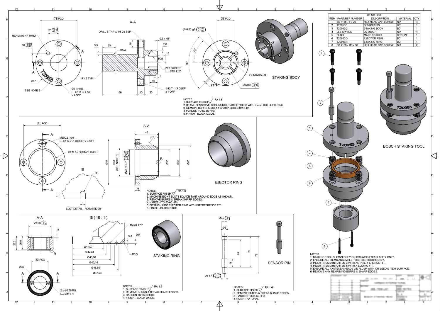
Mechanical Drawing With Dimension An engineering drawing provides details such as first angle projections, hidden lines, extension lines, etc., which are crucial for precise manufacturing. they include cross sectional views or an auxiliary view that reveal hidden features and internal details, which a 3d model alone cannot fully convey. while 3d models are valuable for visual. System, and type of drawing. the drawing number may also contain information such as the sheetnumber,if the drawingis partof a series, or it may containthe revision level. drawings areusuallyfiled by theirdrawing number becaus e thedrawingtitle may be commont o severalprints or series of prints. second area of the title block. 14 february 2000 for use by the department of defense (dod). proposed changes by dod activities must be submitted to the dod adopting activity: commander, u.s. army ardec, attn: rdar qes e, picatinny arsenal, nj 07806 5000. copies of this document may be purchased from the american society of mechanical engineers (asme), three park avenue new. Engineering drawing basics explained. an engineering drawing is a subcategory of technical drawings. the purpose is to convey all the information necessary for manufacturing a product or a part. engineering drawings use standardised language and symbols. this makes understanding the drawings simple with little to no personal interpretation.

30 Mechanical Workings Drawing Reference Ideas Mechanical Design Working 14 february 2000 for use by the department of defense (dod). proposed changes by dod activities must be submitted to the dod adopting activity: commander, u.s. army ardec, attn: rdar qes e, picatinny arsenal, nj 07806 5000. copies of this document may be purchased from the american society of mechanical engineers (asme), three park avenue new. Engineering drawing basics explained. an engineering drawing is a subcategory of technical drawings. the purpose is to convey all the information necessary for manufacturing a product or a part. engineering drawings use standardised language and symbols. this makes understanding the drawings simple with little to no personal interpretation. Basic dimensions are typically used within the gd&t framework to control the location or geometry of features. the best example of when basic dimensions are used is when specifying true position. take a look at this drawing below: the basic dimensions are those dimensions in the boxes – the 30 and the 15. they do have tolerances, though, as. Powerpoint presentation. asme y14.24: this standard defines the types of engineering drawings most frequently used to establish engineering requirements. it describes typical applications and minimum content requirements. drawings for specialized engineering disciplines (e.g., marine, civil, construction, optics, etc.) are not included in this.

Mechanical Engineer Drawing At Getdrawings Free Download Basic dimensions are typically used within the gd&t framework to control the location or geometry of features. the best example of when basic dimensions are used is when specifying true position. take a look at this drawing below: the basic dimensions are those dimensions in the boxes – the 30 and the 15. they do have tolerances, though, as. Powerpoint presentation. asme y14.24: this standard defines the types of engineering drawings most frequently used to establish engineering requirements. it describes typical applications and minimum content requirements. drawings for specialized engineering disciplines (e.g., marine, civil, construction, optics, etc.) are not included in this.

Comments are closed.