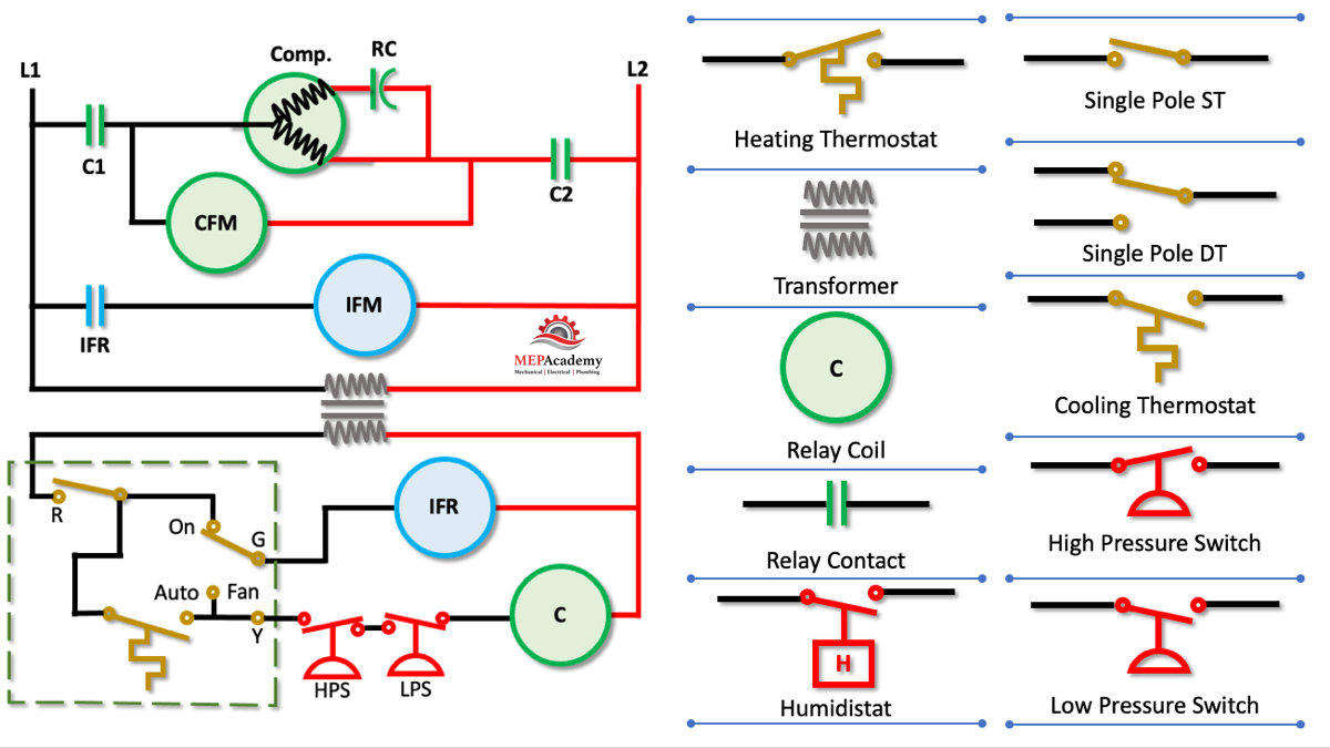
Electrical Wiring Diagram Of Heating And Cooling System

Wiring Diagrams Of Heating Equipment R or rc wire (power) connected to the r power terminal to power the thermostat. w wire (heat), connected to the heating control. g wire (fan) connected to the fan control to operate a blower in your hvac system. y1 wire (cooling) connected to the y terminal compressor refrigerant system. An hvac wiring diagram is a visual representation of the electrical components and their connections in a heating, ventilation, and air conditioning system. it is an essential tool for understanding and troubleshooting the electrical system of an hvac system. the diagram illustrates the flow of electrical current and provides a detailed.

Electrical Wiring Diagrams For Air Conditioning Systems вђ Part Two ођ Hvac control wiring diagram is an essential tool that is used in the installation and troubleshooting of heating, ventilation, and air conditioning systems. it provides a visual representation of the electrical components and their interconnections, allowing hvac technicians to understand how the system operates and diagnose any issues that may. 1 importance of electrical wiring for air conditioning systems. in the detailed design phase, the electrical designer must size and select the wires cables, conduits, starters, disconnects and switchgear necessary for supplying power and control to hvac equipment. this information designed by the electrical designer will be and must appear on. In the hvac (heating, ventilation, and air conditioning) industry, understanding wiring diagrams is crucial for technicians and installers. these diagrams provide a visual representation of the electrical connections and components involved in an hvac system, allowing professionals to troubleshoot and repair any issues effectively. Follow the manufacturer’s instructions for connecting the thermostat wiring to the heating system. run the wiring: using the appropriate cable size, run the wiring from the thermostat to the heating system. it’s important to keep the wiring secured and away from any sharp edges or moving parts to avoid damage.

How To Read Wiring Diagrams In Hvac Systems Mep Academy In the hvac (heating, ventilation, and air conditioning) industry, understanding wiring diagrams is crucial for technicians and installers. these diagrams provide a visual representation of the electrical connections and components involved in an hvac system, allowing professionals to troubleshoot and repair any issues effectively. Follow the manufacturer’s instructions for connecting the thermostat wiring to the heating system. run the wiring: using the appropriate cable size, run the wiring from the thermostat to the heating system. it’s important to keep the wiring secured and away from any sharp edges or moving parts to avoid damage. The hvac wiring diagram thermostat illustrates the electrical connections between the thermostat, the heating or cooling system, and the power supply. it shows the different wires and terminals involved in the system and their corresponding functions. the diagram provides a visual representation of how the thermostat interacts with the hvac. Understanding hvac wiring diagrams is essential for professionals working in the heating, ventilation, and air conditioning industry. these diagrams are like blueprints that offer a visual representation of the electrical wiring in hvac systems. it’s crucial to comprehend these diagrams to troubleshoot, repair, and install hvac equipment.

Comments are closed.