Dynamic Power Dissipation In Cmos Vlsi System Design

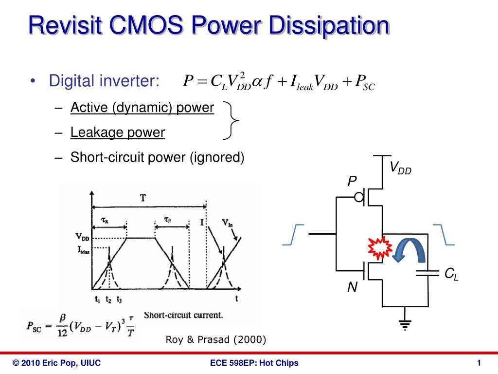
Dynamic Power Dissipation In Cmos Vlsi System Design In that area, if gate input rises from 0v to (say) 0.5v, the vgs of nmos is 0.5v, which is just above the threshold voltage of nmos (assuming nmos vt is 0.2v for 180nm technology node), so it just turns on. now the vgs of pmos is roughly, say 0.5v – 1.8v = 1.3v which is again, far above threshold voltage of pmos transistor, so your pmos. Review: dynamic power. each charge discharge cycle dissipates total energy e = c v 2 vdd l dd. to compute power, account for switching the circuit at frequency f. typically, output does not switch every cycle, so we scale the power by the probability of a transition α.

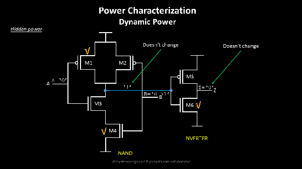
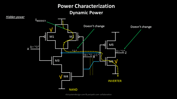
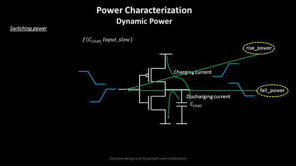
Dynamic Power Dissipation In Cmos Vlsi System Design 7: power cmos vlsi design 4th ed. 11 dynamic power example 1 billion transistor chip – 50m logic transistors • average width: 12 λ • activity factor = 0.1# – 950m memory transistors • average width: 4 λ • activity factor = 0.02# – 1.0 v 65 nm process – c = 1 ff µm (gate) 0.8 ff µm (diffusion). Meet me, i am “hidden power” dynamic power dissipation in cmos when we are asked about dynamic power dissipation, below 2 things just appear at the top of our mind: switching power dissipation the word ‘switching’ over here means a lot. it’s not just that inputs are switching, it’s the outputs also. The power consumed in a vlsi circuit can be broadly classified into two types – static power dissipation and dynamic power dissipation. 1. static power. static power is the power consumed when there is no circuit activity or you can say, when the circuit is in quiescent mode. in the presence of a supply voltage, even if we withdraw the clocks. The cmos dynamic power is the power dissipated when the logic gate is in the active state. it is mainly due to the switching activity of the i p signal or mainly due to the charging and discharging of internal node capacitances. pdynamic = ∝ * cl * (vdd)^2 * f. the cmos dynamic power (pdynamic) dissipation is mainly due to.
Sources Of Power Dissipation In Cmos Vlsi Physical Design For Freshers The power consumed in a vlsi circuit can be broadly classified into two types – static power dissipation and dynamic power dissipation. 1. static power. static power is the power consumed when there is no circuit activity or you can say, when the circuit is in quiescent mode. in the presence of a supply voltage, even if we withdraw the clocks. The cmos dynamic power is the power dissipated when the logic gate is in the active state. it is mainly due to the switching activity of the i p signal or mainly due to the charging and discharging of internal node capacitances. pdynamic = ∝ * cl * (vdd)^2 * f. the cmos dynamic power (pdynamic) dissipation is mainly due to. Effective power management is possible by using the different strategies at various levels in vlsi design process. so designers need an intelligent approach for optimizing power consumptions in designs. 3. power dissipation basics in a circuit three components are responsible for power dissipation: dynamic power, short circuit. A clock in a system has an activity factor α=1, since it rises and falls every cycle. most data has an activity factor of 0.1. if correct load capacitance is estimated on a node together with its activity factor, the dynamic power dissipation at that node can be calculated effectively.

Dynamic Power Dissipation In Cmos Vlsi System Design Effective power management is possible by using the different strategies at various levels in vlsi design process. so designers need an intelligent approach for optimizing power consumptions in designs. 3. power dissipation basics in a circuit three components are responsible for power dissipation: dynamic power, short circuit. A clock in a system has an activity factor α=1, since it rises and falls every cycle. most data has an activity factor of 0.1. if correct load capacitance is estimated on a node together with its activity factor, the dynamic power dissipation at that node can be calculated effectively.

Cmos Inverter Using Vlsi Presentation

Comments are closed.