Define Reference Line In Engineering Drawing

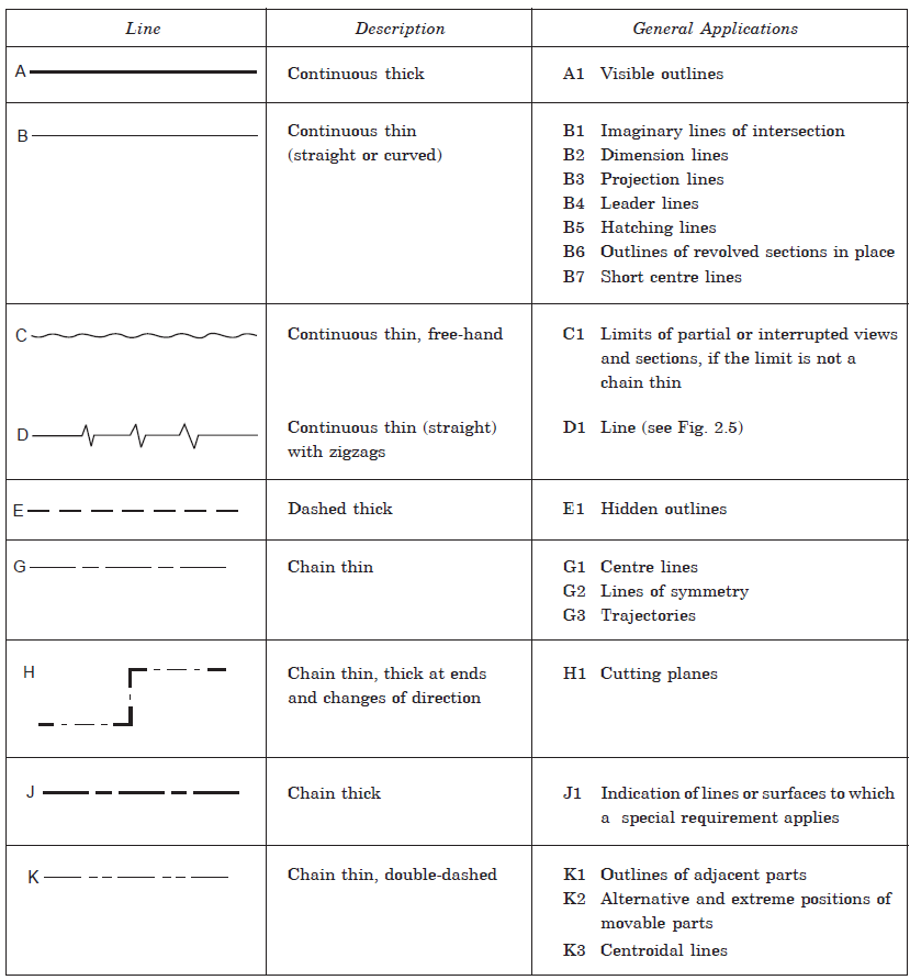
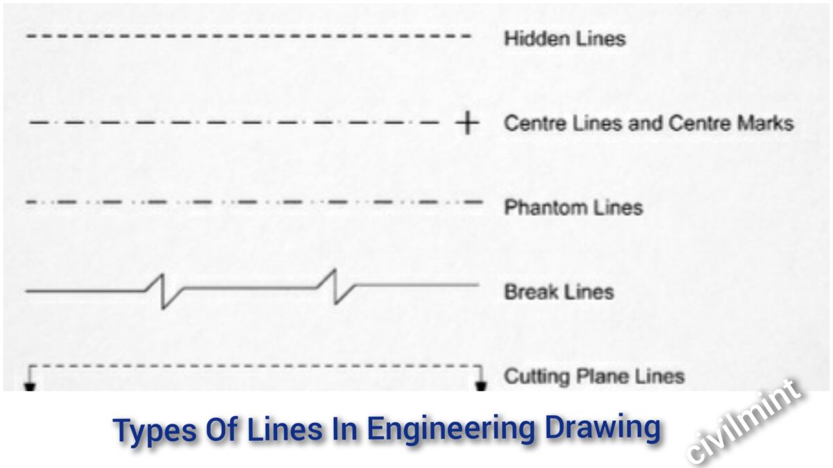
Engineering Drawing Lines The dashed line may be either thick or thin, but only one type (thick or thin) should be used on a single drawing or set of drawings. thin chain line. the thin chain line is used to indicate center lines, the lines of symmetry and also trajectories. often this line is used as a point of reference on engineering drawings. thin chain line with. Straight and curved lines are parallel when the shortest distance between them remains constant. again, lines are differentiated as thick lines (0.6 mm thickness), thin lines (0.3 mm thick), continuous lines, dashed lines, freehand lines, zigzag lines, chain lines, etc. in this article, we will learn the various types of lines that are widely.

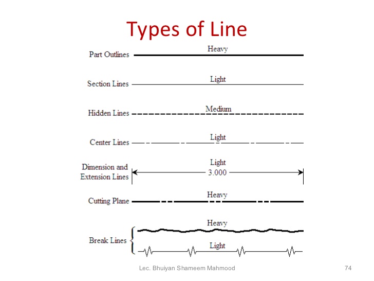
Engineering Drawing Line Inclined To Both The Reference Planes Youtube Leader lines. orthographic projection lines. section lines. visible lines. these are various types of lines commonly used in technical drawings, engineering, and architectural drafting: break lines: break lines are used to represent a long object or feature that is too large to be shown in its entirety on a drawing. Following are the different types of lines used in engineering drawing: a type – continuos thick. b type – continuous thin. c type – continuous thin freehand. d type – continuous thin zig zag. e type – dashes thick. f type – dashes thin. g type – chain thin. h type – chain thin and thick. It is a line! in graphics communication practice there is the whole collection of different lines, which are used for drawing purposes. the alphabet of lines is a set of standard line types established by the american national standards institute (ansi) for technical drawing. the alphabet of lines and the approximate dimensions used to create. The thickness relates to the importance of the line on a drawing. the typical leads used are h, 2h, 4h (2 mm), and or 0.03 mm, 0.05 mm, 0.07 mm, and 0.09 mm. line weight on a drawing varies from a thin line to a thicker line. the line types typically used on nkba drawings are illustrated in figure 1. figure 1 line types used on floor plan.

Engineering Drawing 8 Tips To Improve Engineering Drawing Skills It is a line! in graphics communication practice there is the whole collection of different lines, which are used for drawing purposes. the alphabet of lines is a set of standard line types established by the american national standards institute (ansi) for technical drawing. the alphabet of lines and the approximate dimensions used to create. The thickness relates to the importance of the line on a drawing. the typical leads used are h, 2h, 4h (2 mm), and or 0.03 mm, 0.05 mm, 0.07 mm, and 0.09 mm. line weight on a drawing varies from a thin line to a thicker line. the line types typically used on nkba drawings are illustrated in figure 1. figure 1 line types used on floor plan. The width of the line should be chosen from one of the following. 0.13 mm, 0.18mm, 0.25 mm, 0.35 mm, 0.50mm, 0.70mm, 1.0mm, 1.4 mm, and 2.0 mm. the series is based on the common ratio of 1:√2 or 1:1.4. generally, lines of three different widths specified as extra wide, wide, and narrow lines are used in engineering drawing works. The dimension line is a thin line, broken in the middle to allow the placement of the dimension value, with arrowheads at each end (figure 23). figure 23 dimensioned drawing. an arrowhead is approximately 3 mm long and 1 mm wide. that is, the length is roughly three times the width. an extension line extends a line on the object to the.

Types Of Lines In Engineering Drawing Civilmint Com The width of the line should be chosen from one of the following. 0.13 mm, 0.18mm, 0.25 mm, 0.35 mm, 0.50mm, 0.70mm, 1.0mm, 1.4 mm, and 2.0 mm. the series is based on the common ratio of 1:√2 or 1:1.4. generally, lines of three different widths specified as extra wide, wide, and narrow lines are used in engineering drawing works. The dimension line is a thin line, broken in the middle to allow the placement of the dimension value, with arrowheads at each end (figure 23). figure 23 dimensioned drawing. an arrowhead is approximately 3 mm long and 1 mm wide. that is, the length is roughly three times the width. an extension line extends a line on the object to the.

Comments are closed.