Continuous Cooling Transformation Diagram Titanium

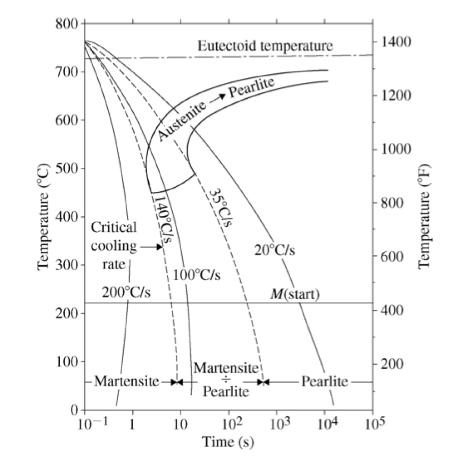
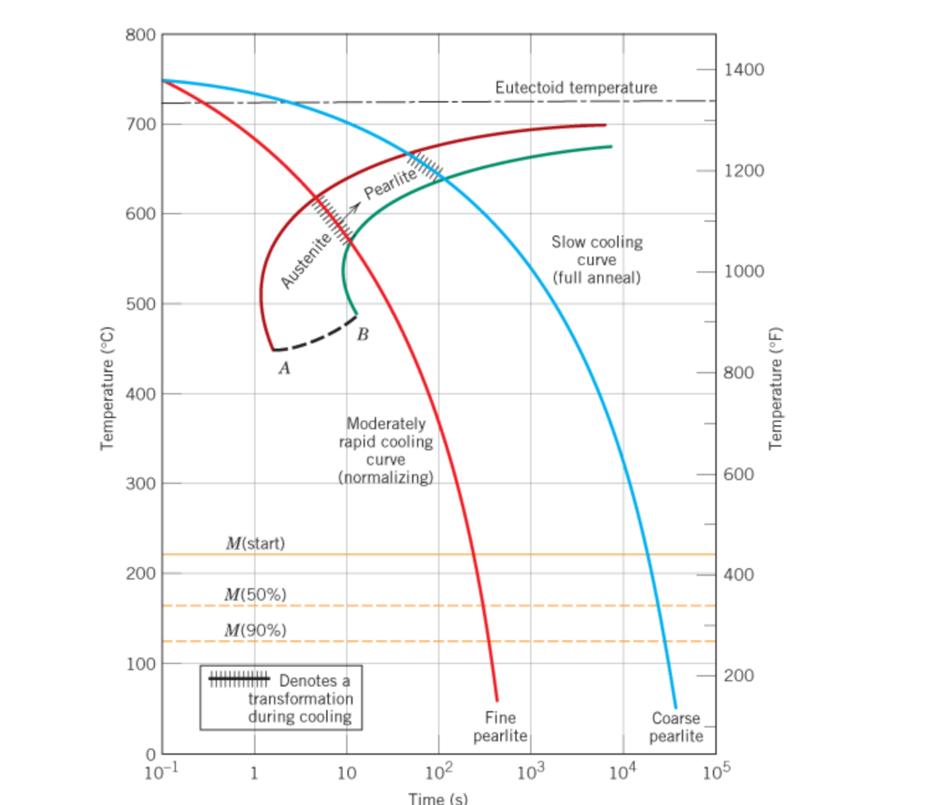
Continuous Cooling Transformation Cct Diagram For Ti6al4v The Three Download Definition: stability of phases during continuous cooling of austenite. there are two types of cct diagrams. i) plot of (for each type of transformation) transformation start, specific fraction of transformation and transformation finish temperature against transformation time on each cooling curve. As shown in figure 3, after the fast cooling, such as water cooling with a rate around 1000 • c s, the microstructure can be fully transformed into α martensite. the air cooling rate is as.

Continuous Cooling Transformation Diagram Based on the samples quenched from high temperatures, the microstructures during continuous cooling was characterized and the cct diagram was established and evaluated. with the increase of cooling rate (5, 20, 100, 700 k min), the phase transformation presented a lagging behavior comparing with the equilibrium phase diagram. A continuous cooling phase diagram related to the cooling rate was established, which can further quantify and characterize the corresponding relationship between the cooling rate and the phase transformation mechanism, and guide the formulation of continuous cooling process for titanium alloy. The phase transformations of ti 5al 2sn 4zr 4mo 2cr 1fe (β cez) have been studied during continuous cooling after β solution treatment. for this purpose, electrical resistivity measurements and metallographical examinations have been carried out, and the continuous cooling transformation (cct) diagram of β cez alloy has been plotted. the different kinds of β phase decomposition schemes in. Fig. 1 presents sem bse images of ti 40nb and tmzf. in fig. 1, it can be observed that while the ti 40nb cooled to 50 k s (fig. 1 a, and 1 c) showed α″ dispersed in the β matrix, the tmzf cooled to 0.05 k s (fig. 1 b, and 1 d) presented α phase dispersed in the β matrix.

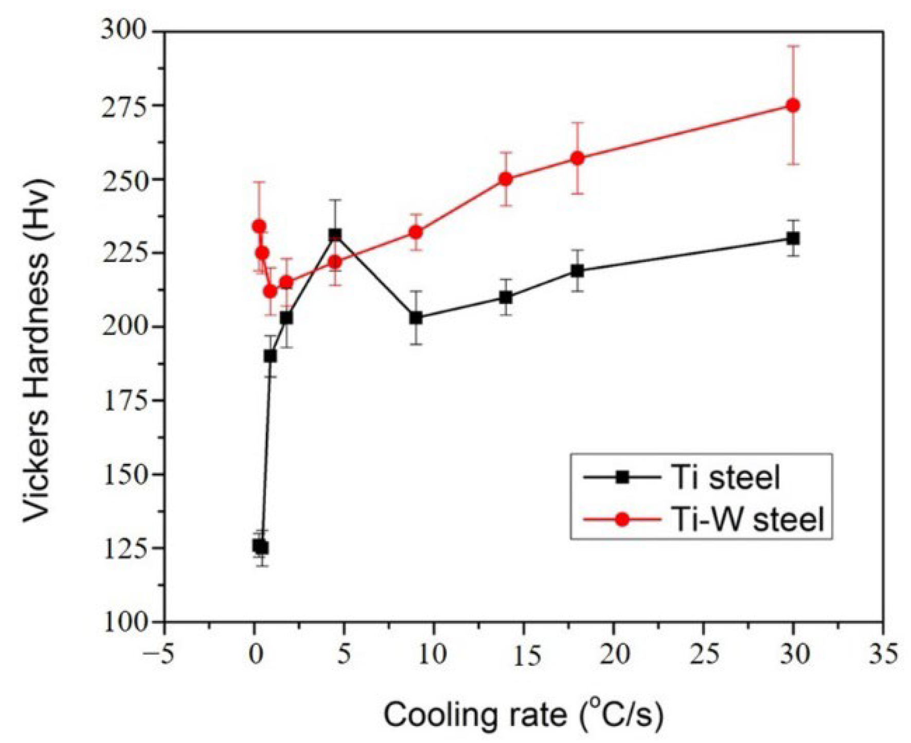
Metals Free Full Text Effect Of Tungsten Addition On Continuous Cooling Transformatio The phase transformations of ti 5al 2sn 4zr 4mo 2cr 1fe (β cez) have been studied during continuous cooling after β solution treatment. for this purpose, electrical resistivity measurements and metallographical examinations have been carried out, and the continuous cooling transformation (cct) diagram of β cez alloy has been plotted. the different kinds of β phase decomposition schemes in. Fig. 1 presents sem bse images of ti 40nb and tmzf. in fig. 1, it can be observed that while the ti 40nb cooled to 50 k s (fig. 1 a, and 1 c) showed α″ dispersed in the β matrix, the tmzf cooled to 0.05 k s (fig. 1 b, and 1 d) presented α phase dispersed in the β matrix. The 2 mm sheets were rolled in the single β phase field region and subsequently cooled in air. a continuous cooling transformation (cct) diagram was generated, revealing the strong influence of the cooling rate on both microstructure and hardness. cooling rates between 0.01 and 200°c s −1 were selected. while rapid cooling resulted in a. The continuous cooling transformation (cct) diagram of this alloy was achieved by x ray diffractometer (xrd), scanning electron microscopy (sem) and micro hardness analyses. the effect of cooling.

Continuous Cooling Transformation Diagram The 2 mm sheets were rolled in the single β phase field region and subsequently cooled in air. a continuous cooling transformation (cct) diagram was generated, revealing the strong influence of the cooling rate on both microstructure and hardness. cooling rates between 0.01 and 200°c s −1 were selected. while rapid cooling resulted in a. The continuous cooling transformation (cct) diagram of this alloy was achieved by x ray diffractometer (xrd), scanning electron microscopy (sem) and micro hardness analyses. the effect of cooling.

Comments are closed.