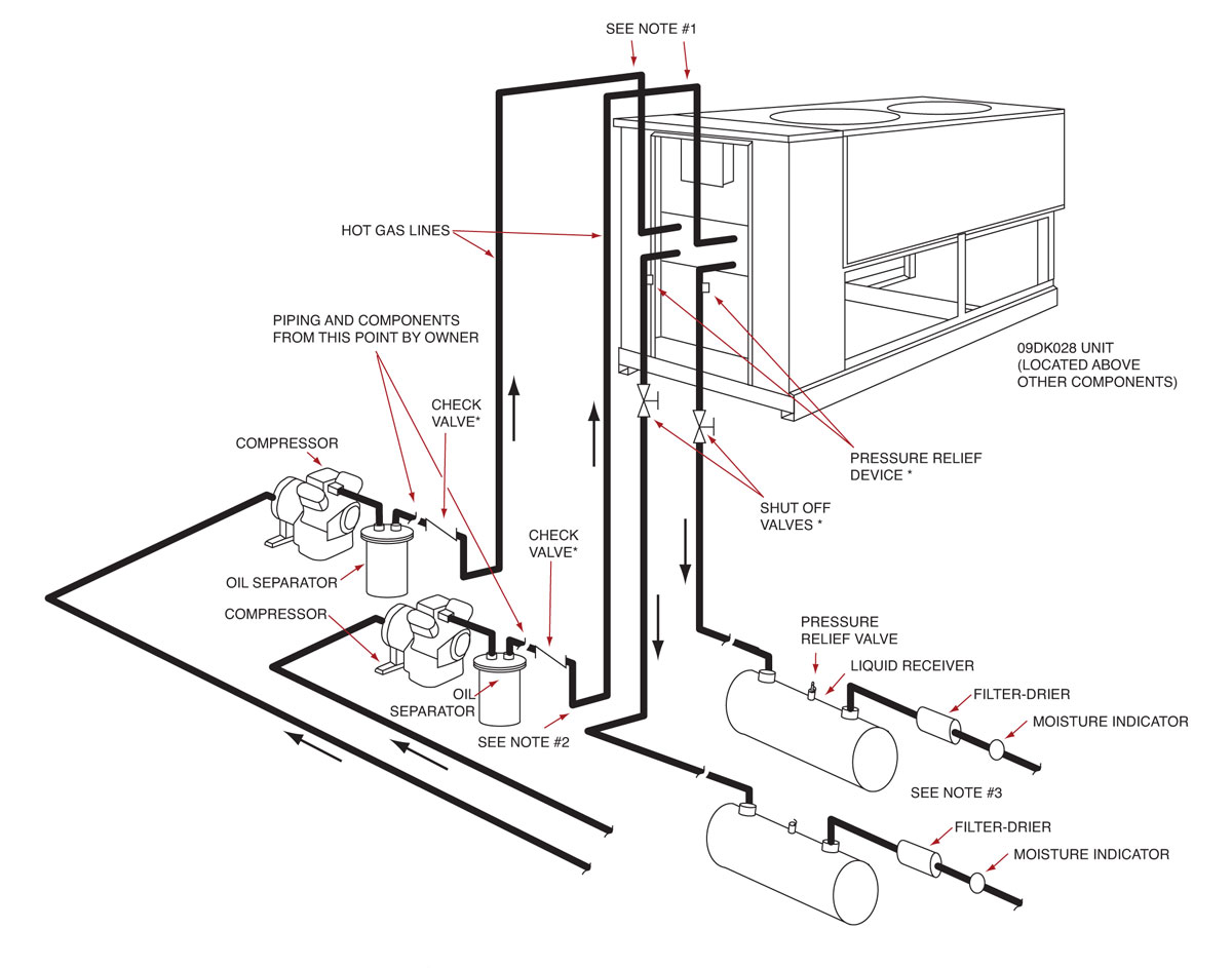
Condenser Water Pipe Schematics How To Read Hvac Engineering Drawing

Condenser Water Pipe Schematics How To Read Hvac Engineering Drawing Youtube Chilled water schematic and condenser water schematic, how to read and understand the engineering drawings with real world examples, illustrations, animations and video tutorial. covering chillers, pump sets, ahus, risers, primary and secondary systems, cooling towers and bypass lines. Chilled water schematics, in this video we look at how to read a chilled water schematic for central plant chilled water system covering chillers, cooling to.
Condenser Water Pipe Schematics How To Read Hvac Engineering Drawing Video Dailymotion This is an hvac system tutorial video about the "how to read hvac drawings?" part 5 regarding the hvac system piping schematic including condenser water and. A condenser water piping diagram is a schematic representation of the layout and components of a condenser water system. it provides a visual guide for designing and constructing the system, as well as for troubleshooting and maintenance purposes. 1. chillers: the chiller is the heart of the condenser water system. A chiller is made up of the 4 major components required for the refrigeration process which are: a) compressor, b) condenser, c) evaporator and d) expansion valve. to produce chilled water, the refrigerant absorbs heat from the water and thus, chilling the water to about 6.7°c (44°f). Sequence of operation. when the operating fan(s) are operating at 50 percent speed, an additional fan shall be enabled and controlled at the same speed as the operating fans until all active cooling tower cell fans are enabled. when operating fans are running at minimum speed and the tower supply water temperature is five (5) degrees below the.

Condenser Piping Diagram A chiller is made up of the 4 major components required for the refrigeration process which are: a) compressor, b) condenser, c) evaporator and d) expansion valve. to produce chilled water, the refrigerant absorbs heat from the water and thus, chilling the water to about 6.7°c (44°f). Sequence of operation. when the operating fan(s) are operating at 50 percent speed, an additional fan shall be enabled and controlled at the same speed as the operating fans until all active cooling tower cell fans are enabled. when operating fans are running at minimum speed and the tower supply water temperature is five (5) degrees below the. Flexible duct size and quantity. chilled water pipe size and route. control panel location and quantity. damper type, quantity and location. thermostat location and quantity. most of the time, layout drawings are used to see the location of the hvac equipment. besides, they are useful for site coordination to prevent clashes of services. Ceeding energy code minimum requirements. a comprehensive approach to system design can minimize the power draw of the entire system are inherently easier to control for highest eficiency, lower first costs and lower energy costs. right sizing equipment means smaller electrical conne. tions—a great way to do m.

Condenser Piping Diagram Flexible duct size and quantity. chilled water pipe size and route. control panel location and quantity. damper type, quantity and location. thermostat location and quantity. most of the time, layout drawings are used to see the location of the hvac equipment. besides, they are useful for site coordination to prevent clashes of services. Ceeding energy code minimum requirements. a comprehensive approach to system design can minimize the power draw of the entire system are inherently easier to control for highest eficiency, lower first costs and lower energy costs. right sizing equipment means smaller electrical conne. tions—a great way to do m.

Comments are closed.