1994 F250 Transmission Cooling System Diagram

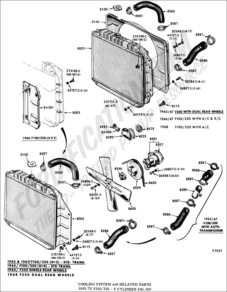
Diagram Ford F 250 Cooling System Diagram Mydiagram Online Cooling, heating, ventilation & a c 1994 ford f250 xlt, 7.5l, complete vacuum diagram needed i was given this 1994 ford f250 with a 7.5 liter (460 cid), automatic transmission, from my brother. overall, a pretty nice truck, but does have its problems. i had worked as an automotive school bus truck mechanic for. Voltage regulator. instrument panel. starter and drive. distributor. distributor modulator system. transmission regulated spark system. headlamp parking lamp taillamps.

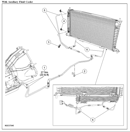
Ford F250 Transmission Cooler Lines Received 189 likes on 147 posts. cooler lines. you need 5 16” tubing. napa has tubing in various lengths with the fittings. or you could use good quality 5 16” hose with barb fittings. reply like. # 3. 03 31 2018, 10:42 am. ultraranger. Cooling system capacity inline six cylinder engines: 14 qts: 232 cu in v6 engines: 12 qts: 255 and 302 cu in engines: 14 qts: 351 and 400 cu in engines: 16 qts: 460 cu in engines: 17.5 qts ** cooling system capacities vary depending on engine transmission package, radiator and a c system type. add coolant as necessary to bring to appropriate level. Ford truck enthusiasts forums. older, classic & antique trucks. 1987 1996 f150 & larger f series trucks. diagram for c6 transmission. notices. 1987 1996 f150 & larger f series trucks 1987 1996 ford f 150, f 250, f 350 and larger pickups including the 1997 heavy duty f250 f350 trucks. As already mentioned, the flow direction of the transmission cooler is such that the top hose attachment is the hotline, and the bottom one is the cold line. the hotline is the fluid returning from the transmission, and the cold line is the fluid returning into the transmission. however, that’s just a rule of thumb, so it could be the other.

I Need A Specific Location For A Coolant Temp Sensor On A 1994 Ford F250 7 3l Turb Ford truck enthusiasts forums. older, classic & antique trucks. 1987 1996 f150 & larger f series trucks. diagram for c6 transmission. notices. 1987 1996 f150 & larger f series trucks 1987 1996 ford f 150, f 250, f 350 and larger pickups including the 1997 heavy duty f250 f350 trucks. As already mentioned, the flow direction of the transmission cooler is such that the top hose attachment is the hotline, and the bottom one is the cold line. the hotline is the fluid returning from the transmission, and the cold line is the fluid returning into the transmission. however, that’s just a rule of thumb, so it could be the other. That line goes into one side of the oil to water cooler in the bottom of the radiator. the outlet from the radiator goes into one side of the oil to air cooler. the outlet from that cooler returns through the rear line on the transmission. the 6.0 cooler is the best upgrade. December 4, 2022. the 6.0 powerstroke transmission cooler lines diagram is a detailed illustration of the transmission cooler lines for the 6.0l powerstroke engine. this diagram provides a clear and concise visual guide for properly routing the cooler lines during installation or replacement. allowing for easy identification of any potential.
Ford F 250 Cooling System Diagram That line goes into one side of the oil to water cooler in the bottom of the radiator. the outlet from the radiator goes into one side of the oil to air cooler. the outlet from that cooler returns through the rear line on the transmission. the 6.0 cooler is the best upgrade. December 4, 2022. the 6.0 powerstroke transmission cooler lines diagram is a detailed illustration of the transmission cooler lines for the 6.0l powerstroke engine. this diagram provides a clear and concise visual guide for properly routing the cooler lines during installation or replacement. allowing for easy identification of any potential.

Comments are closed.